LUFTWAFFE RESOURCE CENTER > FIGHTERS/DESTROYERS > BF 109 > VARIANTS > PREVIOUS PAGE
Variants - Bf 109F - Friedrich

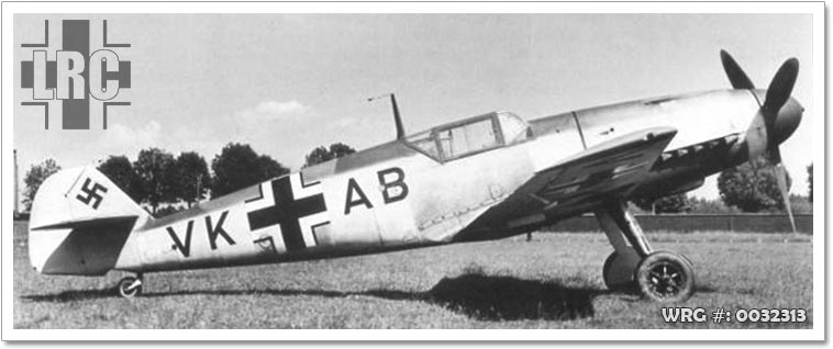
Bf 109 V24, Coded VK+AB, WkNr 5604.
[Source: Unknown]
Compared to the earlier Bf 109 E, the Bf 109 F was much improved aerodynamically. The engine cowling was redesigned to be smoother and more rounded. The enlarged propeller spinner, adapted from that of the new Messerschmitt Me 210, now blended smoothly into the new engine cowling. Underneath the cowling was a revised, more streamlined oil cooler radiator and fairing. A new ejector exhaust arrangement was incorporated, and on later aircraft a metal shield was fitted over the left hand banks to deflect exhaust fumes away from the supercharger air-intake. The supercharger air-intake was, from the F-1 -series onwards, a rounded, "elbow"-shaped design that protruded further out into the airstream. A new three-blade, light-alloy VDM propeller unit with a reduced diameter of 3 m (9 ft 8.5 in) was used. Propeller pitch was changed electrically, and was regulated by a constant-speed unit, though a manual override was still provided. Thanks to the improved aerodynamics, more fuel-efficient engines and the introduction of light-alloy versions of the standard Luftwaffe 300 litre drop tank, the Bf 109 F offered a much increased maximum range of 1,700 km (1,060 mi) compared to the Bf 109 E's maximum range figure of only 660 km (410 miles) on internal fuel, and with the E-7's provision for the 300 litre drop tank, a Bf 109E so equipped possessed double the range, to 1,325 km (820 mi). The canopy stayed essentially the same as that of the E-4, although the handbook for the 'F' stipulated that the forward, lower triangular panel to starboard was to be replaced by a metal panel with a port for firing signal flares. Many F-1s and F-2s kept this section glazed. A two-piece, all-metal armour plate head shield was added, as on the E-4, to the hinged portion of the canopy, although some lacked the curved top section. A bullet-resistant windscreen could be fitted as an option. The fuel tank was self-sealing, and around 1942 Bf 109Fs were retrofitted with additional armour made from layered light-alloy plate just aft of the pilot and fuel tank. The fuselage aft of the canopy remained essentially unchanged in its externals. The tail section of the aircraft was redesigned as well. The rudder was slightly reduced in area and the symmetrical fin section changed to an airfoil shape, producing a sideways lift force that swung the tail slightly to the left. This helped increase the effectiveness of the rudder, and reduced the need for application of right rudder on takeoff to counteract torque effects from the engine and propeller. The conspicuous bracing struts were removed from the horizontal tailplanes which were relocated to slightly below and forward of their original positions. A semi-retractable tailwheel was fitted and the main undercarriage legs were raked forward by six degrees to improve the ground handling. An unexpected structural flaw of the wing and tail section was revealed when the first F-1s were rushed into service; some aircraft crashed or nearly crashed, with either the wing surface wrinkling or fracturing, or by the tail structure failing. In one such accident, the commander of JG 2 "Richthofen", Wilhelm Balthasar, lost his life when he was attacked by a Spitfire during a test flight. While making an evasive manoeuvre, the wings broke away and Balthasar was killed when his aircraft hit the ground. Slightly thicker wing skins and reinforced spars dealt with the wing problems. Tests were also carried out to find out why the tails had failed, and it was found that at certain engine settings a high-frequency oscillation in the tailplane spar was overlapped by harmonic vibrations from the engine; the combined effect being enough to cause structural failure at the rear fuselage/fin attachment point. Initially, two external stiffening plates were screwed onto the outer fuselage on each side, and later the entire structure was reinforced. The entire wing was redesigned, the most obvious change being the new quasi-elliptical wingtips, and the slight reduction of the aerodynamic area to 16.05 m² (172.76 ft²). Other features of the redesigned wings included new leading edge slats, which were slightly shorter but had a slightly increased chord; and new rounded, removable wingtips which changed the planview of the wings and increased the span slightly over that of the E-series. Frise-type ailerons replaced the plain ailerons of the previous models. The 2R1 profile was used with a thickness-to-chord ratio of 14.2% at the root reducing to 11.35% at the last rib. As before, dihedral was 6.53°. The wing radiators were shallower and set farther back on the wing. A new cooling system was introduced; this system was automatically regulated by a thermostat with interconnected variable position inlet and outlet flaps that would balance the lowest drag possible with the most efficient cooling. A new radiator, shallower but wider than that fitted to the E was developed. A boundary layer duct allowed continual airflow to pass through the airfoil above the radiator ducting and exit from the trailing edge of the upper split flap. The lower split flap was mechanically linked to the central "main" flap, while the upper split flap and forward bath lip position were regulated via a thermostatic valve which automatically positioned the flaps for maximum cooling effectiveness. In 1941 "cutoff" valves were introduced which allowed the pilot to shut down either wing radiator in the event of one being damaged; this allowed the remaining coolant to be preserved and the damaged aircraft returned to base. However, these valves were delivered to frontline units as kits, the number of which, for unknown reasons, was limited. These cutoff valves were later factory standard fitting for Bf 109 G and K series. Armament
The armament of the Bf 109 F was revised and now consisted of the two synchronized 7.92 mm MG 17s with 500 rpg above the engine plus a Motorkanone cannon firing through the propeller hub. The pilot's opinion on the new armament was mixed: Oberst Adolf Galland criticised the light armament as inadequate for the average pilot, while Major Walter Oesau preferred to fly a Bf 109 E, and Oberst Werner Mölders saw the single centreline Motorkanone gun as an improvement. With the early tail unit problems out of the way, pilots generally agreed that the F series was the best-handling of all the Bf 109 series. Mölders flew one of the first operational Bf 109 F-1s over England from early October 1940; he may well have been credited with shooting down eight Hurricanes and four Spitfires while flying WkNo 5628, Stammkennzeichen SG+GW between 11 and 29 October 1940. Bf 109F-0, F-1, & F-2
As the DB 601 E was not yet available in numbers, the pre-production F-0 (the only F variant to have a rectangular supercharger intake) and the first production series F-1/F-2 received the 1,175 PS (1,159 hp, 864 kW) DB 601N engine driving a VDM 9-11207 propeller. The F-0/F-1 and F-2 only differed in their armament; the F-1 being fitted with one 20 mm MG FF/M Motorkanone firing through the engine hub, with 60 rounds. The F-1 first saw action in the Battle of Britain in October 1940 with JG 51. The most experienced fighter aces, like Werner Mölders, were the first ones to fly the first Bf 109 F-1s in combat in October 1940. A total of 208 F-1s were built between August 1940 and February 1941 by Messerschmitt Regensburg and the Wiener Neustädter Flugzeugwerke. The F-2 introduced the 15 mm Mauser MG 151 cannon with 200 rounds. The Motorkanone was supplemented by two synchronized 7.92 mm MG 17 machine guns mounted under the engine cowl, with 500 rpg. As the harder-hitting 20 mm version of the same gun become available, a number of F-2s were retrofitted with it in the field. About 1,380 F-2s were built between October 1940 and August 1941 by AGO, Arado, Erla, Messerschmitt Regensburg and WNF. No tropicalized version was built, although individual F-2s were retrofitted with sand filters in the field. The maximum speed of the F-1 and F-2 was 615 km/h (382 mph) at rated altitude. • F-0 (Pre-production aircraft built from E series airframes)
• F-1 (Armed with 1 × 20 mm MG FF/M cannon and 2 × 7.92 mm MG 17
machine guns)
• F-2 (Armed with 1 × 15 mm MG 151 cannon and 2 × 7.92 mm MG 17)
– F-2 trop (tropicalized version, only as field conversion)
– F-2/Z (high-altitude fighter with GM-1 boost, cancelled in favour of the F-4/Z) Bf 109F-3 through F-6
The 1,350 PS (1,332 hp, 993 kW) DB 601 E was used in the F-3 and F-4 model together with a VDM 9-12010 propeller with broader blades for improved altitude performance. The DB 601 E was initially restricted to 1,200 PS (1,184 hp, 883 kW) at 2,500 rpm; however, the full rating of 1,350 PS at 2,500 rpm was cleared for service use by February 1942. The DB 601 E ran on standard 87 octane "B-4" aviation fuel, despite its increased performance; while the earlier DB 601 N required 100 octane "C-3" fuel. Only 15 examples of the F-3 are believed to have been produced by Messerschmitt Regensburg between October 1940 and January 1941. Like the F-1, the F-3 was armed with the 20 mm MG-FF/M and two 7.92 mm MG 17s.

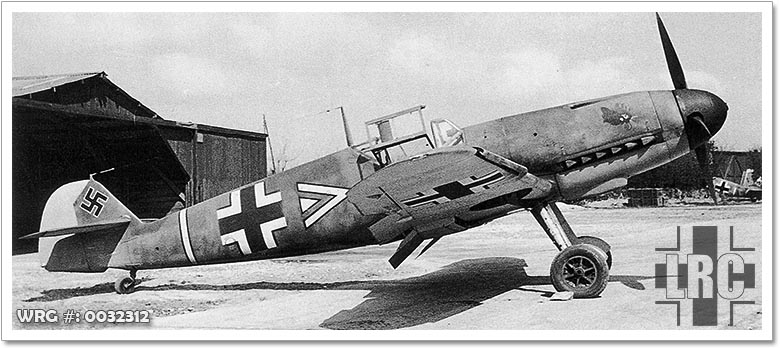
Messerschmitt Bf 109F-4.
[Source: Unknown]
• F-4 (As F-2 but with DB 601E engine, 20 mm MG 151/20 cannon replacing
the 15 mm MG 151)
– F-4/R1 (As F-4, but capable of mounting two 20 mm MG 151/20 cannons in
underwing gondolas)
– F-4/Z (As F-4, high-altitude fighter with GM-1 boost)
• F-5 (Recon version of F-4, only one prototype known)
• F-6 (planned but not built)
Sources:
Wikipedia
LUFTWAFFE RESOURCE CENTER > FIGHTERS/DESTROYERS > BF 109 > VARIANTS > PREVIOUS PAGE
