|
|
|
U.S.A.A.F. RESOURCE CENTER > FIGHTERS > P-61 BLACK WIDOW > PREVIOUS PAGE
P-61 BLACK WIDOW
Design & Development
Origins
In August 1940, 16 months before the United States entered the war, the U.S. Air Officer in London, Lieutenant General Delos C. Emmons, was briefed on British research in RADAR, which had been underway since 1936 and had played an important role during the Battle of Britain. General Emmons was informed of the new Airborne Intercept radar (AI for short), a self-contained unit that could be installed in an aircraft and allow it to operate independently of ground stations. In September 1940, the Tizard Mission traded British research on many aspects including radar for American production.
Simultaneously, the British Purchasing Commission evaluating US aircraft declared their urgent need for a high-altitude, high-speed aircraft that would require at least an eight-hour loiter capability in order to complete night time patrols. The aircraft would carry one of the early AI radar units, and mount its specified armament in several multiple-gun turrets. The British issued the requirements for the new night-fighter to all the aircraft designers and manufacturers they were working with. The Emmons Board developed the basic requirements and specifications for the night-fighter and handed them over towards the end of 1940 to Air Technical Service Command, Wright Field. Jack Northrop realized early on that the speed, altitude, fuel load and multiple-turret requirements demanded a large aircraft with multiple engines.
On 5 November, Northrop met at Wright Field with Air Material Command officers and presented them with Northrop�s preliminary design. Douglas� XA-26A night fighter proposal was the only competition, but Northrop�s design was selected and the Black Widow was conceived. Following the USAAC acceptance, Northrop began comprehensive design work on the aircraft to become the first to design a dedicated night fighter. The result was the largest and one of the most deadly pursuit-class aircraft flown by the U.S. during the war.
Jack Northrop's first proposal was a long fuselage gondola between two engine nacelles and tail booms. Engines were Pratt & Whitney R-2800-10 Double Wasp 18-cylinder radials, producing 2,000 hp (1,491 kW) each. The fuselage housed the three-man crew, the radar, and two four-gun turrets. The .50 in (12.7 mm) M2 Browning machine guns were fitted with 36 in (91 cm) long "aircraft" barrels with perforated sleeves. The turrets were located in the nose and rear of the fuselage. It stood on tricycle landing gear and featured full-span retractable flaps, or "Zap flaps" (named after Northrop engineer Edward Zap) in the wings.
As Northrop had anticipated the aircraft was large, its 45.5 ft length, 66 ft wingspan and at a projected 22,600 lb full-load weight put the P-61 in the medium bomber catagory. Classifying such a large aircraft as a fighter was hard for some to accept.
Some alternative design features were investigated before finalization. Among them were conversion to a single vertical stabilizer/rudder and the shifting of the nose and tail gun turrets to the top and bottom of the fuselage along with the incorporation of a second gunner.By late in November 1940, Jack Northrop returned to the crew of three and twin tail/rudder assembly. To meet USAAC's request for more firepower, designers abandoned the ventral turret and mounted four 20 mm Hispano M2 cannons in the wings. As the design evolved, the cannons were subsequently repositioned in the belly of the aircraft. The P-61 therefore became one of the few U.S.-designed fighter aircraft to have 20 mm cannons as factory-standard in World War II.
Northrop Specification 8A was formally submitted to Army Air Material Command at Wright Field, on December 5, 1940. Northrop's NS-8A fulfilled all USAAC requirements, and after a few small changes the Air Corps issued Northrop a Letter of Authority For Purchase on December 17, 1940. A contract for two prototypes and two scale models to be used for wind tunnel testing (costs not to exceed $1,367,000), was awarded on January 10, 1941. The War Department officially issued the designation XP-61 for these prototypes.
XP-61 Development
The XP-61 was designed with downdraft carburETOrs, but in March 1941, the Army/Navy Standardization Committee had standardized use of updraft carburETOrs across all U.S. military branches. Northrop was faced an estimated minimum 60-day redesign of the engine nacelle to bring the design into compliance. The committee eventually reversed the standardization decision (the XP-61 program's predicament likely having little influence), allowing the development of the XP-61 to proceed without delay.
The XP-61 mock-up was inspected by the Air Corps Mockup Board on April 2, 1941. They made several recommendations, the `most prominent was to relocate the four 20 mm M2 cannons from the outer wings to the belly of the aircraft. Having them clustered tightly just behind the rear of the nose gear well. The closely spaced, centeral installation, eliminated the inherent drawbacks of convergence and grouped the firepower roughly along the aircraft centerline.
Mounting the weapons on the centerline made aiming considerably easier and faster. The arrangement also a allowed the tightly grouped cannons to create a thick stream of 20 mm projectiles. The removal of the guns and ammunition from the wings also cleaned up the wings' airfoil and increased internal fuel capacity from 540 gallons to 646 gallons. This change, plus addition suggested changes such as the provision for external fuel carriage in drop tanks, flame arrestors/dampers on engine exhausts, and relocation of some radio equipment required over 30 days of redesign work. While all beneficial from a performance standpoint�especially the movement of the cannons, this put the XP-61 behind schedule.
The dorsal turret mount proved very difficult to install in the aircraft, and by mid-1941 it was changed from the General Electric ring mount to a pedestal mount similar to that used for the upper turrets in most of the USAAF bombers then in service. Following this modification, the turret itself became unavailable, as operational aircraft, in this case the Boeing B-29 Superfortress, were prioritized ahead of experimental aircraft. For flight testing a dummy turret was fitted.
Another set back occurred in February 1942 when Curtiss notified Northrop that the C5424-A10 four-bladed, automatic, full-feathering propeller Northrop had planned for use was behind schedule and would not be available for the beginning of flight tests. Hamilton Standard propellers were used temporarily until the Curtiss C5424-A10 propellers became available.
Various design changes during the construction of the prototype caused the the XP-61s weight to rise to 22,392 lb (10,157 kg) empty and 29,673 lb (13,459 kg) at takeoff. The powerplants used were Pratt & Whitney R-2800-25S Double Wasp radials; turning 12 ft 2 in diameter Curtiss C5425-A10 four-blade propellers, both rotating counterclockwise when viewed from the front. Radios included two command radios, SCR-522As, and three other radio sets, the SCR-695A, AN/APG-1, and AN/APG-2. Central fire control for the gun turret was similar to that used on the B-29, the General Electric GE2CFR12A3.
P-61C
After the P-61A and B showed some shortcomings in combat, it was decided to create a high performance variant, the P-61C Black Widow. Work on the C model proceeded slowly at Northrop, mainly because of the Northrop XB-35 flying wing project had a higher priority. To alleviate some of the pressure on the Northrop design team, much of the work on the P-61C was farmed out to Goodyear, which had been a subcontractor for production of Black Widow components. Eventually the first production P-61C-1-NO rolled off the production lines in early 1945. As predicted, there was a substantial performance gain in spite of a 2,000 lb. increase in empty weight. Maximum speed increased to 430 mph at 30,000 ft, service ceiling was 41,000 ft. The climb to an altitude of 30,000 ft could be achieved in less than 15 minutes.
To help prevent overshooting the target during an intercept, the C-Model was equipped with perforated airbrakes located both below and above the wing surfaces. The P-61C was equiped with four plumbed underwing pylons (two inboard of the nacelles, two outboard) which could carry four 310 gallon drop tanks. The first P-61C aircraft was accepted by the USAAF in July 1945 but the war ended before any C-models could see combat. The last P-61C-1-NO was accepted on January 28, 1946. An additional 13 were completed, but were scrapped before they could be being delivered.
The service life of the P-61C was quite brief, quickly being outperformed and replaced in most capacities by jet aircraft. they majority of P-61Cs were scrapped by the end of March 1949.
F-15/RF-16C
The speed and payload capacity made it an ideal candidate for a photographic reconnaissance aircraft. By mid-1945, the surviving XP-61E was modified for this role. Armament was removed and a new nose was fitted, capable of mounting a variety of aerial cameras. This aircraft, redesignated XF-15, flew for the first time on July 3, 1945. A P-61C was also modified to XF-15 standards and apart from the turbosupercharged R-2800-C powerplants, it was identical to the XF-15 and flew for the first time on October 17, 1945. Hughes Tool Company of Culver City, California was awarded the contract for the nose for the F-15A. The F-15A was basically the P-61C with the new bubble-canopy fuselage and the reconnaissance nose, but without the perforated brakes on the wing.
F2T-1N
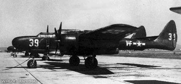
The United States Marine Corps had planned to acquire 75 Black Widows, but these were canceled in 1944 in favor of the Grumman F7F Tigercat. In September 1945, however, the Marines received a dozen former Air Force P-61Bs to serve as radar trainers until the Tigercats would be available in squadron strength. Designated F2T-1N these aircraft were assigned to shore-based Marine units and served briefly, the last two F2T-1s being withdrawn on 30 August 1947.
USMC Northrop F2T-1N Black Widow.
[Source: USMC Photo]
Design
The P-61 featured a crew of three: pilot, gunner, and radar operator. It was armed with four 20 mm (.79 in) Hispano M2 forward firing cannons mounted in the lower fuselage, and four .50 in (12.7 mm) M2 Browning machine guns lined up horizontally with the two middle guns slightly offset upwards in a remotely aimed dorsally mounted turret. The turret was driven by the General Electric GE2CFR12A3 gyroscopic fire control computer, and could be directed by either the gunner or radar operator, who both had aiming control and gyroscopic collimator sight assembly posts attached to their swiveling seats.
The two Pratt & Whitney R-2800-25S Double Wasp engines were each mounted approximately one-sixth out on the wing's span. Two-stage, two-speed mechanical superchargers were fitted. In an effort to save space and weight, no turbo-superchargers were fitted, despite the expected 50 mph (80 km/h) top speed and 10,000 ft (3,048 m) operational ceiling increases.
Main landing gear bays were located at the bottom of each nacelle, directly behind the engine. The two main gear legs were each offset significantly outboard in their nacelles, and retracted towards the tail; oleo scissors faced forwards. Each main wheel was inboard of its gear leg and oleo. Main gear doors were two pieces, split evenly, longitudinally, hinged at inner door's inboard edge and the outer door's outboard edge.
Each engine cowling and nacelle drew back into tail booms that terminated upwards in large vertical stabilizers and their component rudders, each of a shape similar to a rounded right triangle. The leading edge of each vertical stabilizer was faired smoothly from the surface of the tail boom upwards, swept back to 37�. The horizontal stabilizer extended between the inner surfaces of the two vertical stabilizers, and was approximately � the chord of the wing root, including the elevator. The elevator spanned approximately ? of the horizontal stabilizer's width, and in overhead plan view, angled inwards in the horizontal from both corners of leading edge towards the trailing edge approximately 15�, forming the elevator into a wide, short trapezoid. The horizontal stabilizer and elevator assembly possessed a slight airfoil cross-section.
The engines and nacelles were outboard of the wing root and a short "shoulder" section of the wing that possessed a 4� dihedral, and were followed by the remainder of the wing which had a dihedral of 2�. The leading edge of the wing was straight and perpendicular to the aircraft's centerline. The trailing edge was straight and parallel to the leading edge in the shoulder, and tapered forward 15� outboard of the nacelle. Leading edge updraft carburETOr intakes were present on the wing shoulder and the root of the outer wing, with a few inches of separation from the engine nacelle itself. They were very similar in appearance to those on the F4U Corsair�thin horizontal rectangles with the ends rounded out to nearly a half-circle, with multiple vertical vanes inside to direct the airstream properly.
The P-61 did not have ailerons. Aside from the full-span retractable "Zap flaps," all control of the aircraft about the roll axis was maintained through the use of curved, tapered spoilerons, of approximately 10 ft in length and 6 in in width. They were located outboard of the outer edge of each nacelle, approximately � the length of the outer wing panel, and offset towards the wing leading edge approximately one third the wing's chord from the trailing edge, running towards the wing-tip approximately half the length of the outer wing. Operation was as follows: the spoileron in the inside wing rotated out of the wing's upper surface into the airstream and reducing lift over that wing, causing it to drop.
The main fuselage, or gondola, was centered on the aircraft's centerline. It was, from the tip of the nose to the end of the Plexiglas tail-cone, approximately five-sixths the length of one wing (root to tip). The nose housed an evolved form of the SCR-268 Signal Corps Radar, the Western Electric Company's SCR-720A. Immediately behind the radar was the multi-framed "greenhouse" canopy, featuring two distinct levels, one for the pilot and a second for the gunner above and behind him, the latter elevated by approximately 6 in. Combined with the nearly flat upper surface of the aircraft's nose, the two-tiered canopy gave the aircraft's nose a distinct appearance of three wide, shallow steps. The forward canopy in the XP-61 featured contiguous, smooth-curved, blown-Plexiglas canopy sections facing forward, in front of the pilot and the gunner. The tops and sides were framed.
Beneath the forward crew compartment was the nose gear wheel well, through which the pilot and gunner entered and exited the aircraft. The forward gear leg retracted to the rear, up against a contoured cover that when closed for flight formed part of the cockpit floor; the gear would not have space to retract with it open. The oleo scissor faced forwards. The nosewheel was centered, with the strut forking to the aircraft's left. The nosewheel was approximately � the diameter of the main wheels. Nose gear doors were two pieces, split evenly longitudinally, and hinged at each outboard edge.
The center of the gondola housed the main wing spar, fuel storage, fuel piping and control mechanisms, control surface cable sections, propeller and engine controls, and radio/IFF/communications equipment, but was predominantly occupied by the top turret mounting ring, rotation and elevation mechanisms, ammunition storage for the turret's machine guns, the GE2CFR12A3 gyroscopic fire control computer, and linkages to the gunner and radar operator's turret control columns, forward and aft, respectively.
The radar operator's station was at the aft end of the gondola. The radar operator controlled the SRC-720 radar set and viewed its display scopes from the isolated rear compartment, which he entered by way of a small hatch with a built-in ladder on the underside of the aircraft. In addition to the radar systems themselves, the radar operator had intercom and radio controls, as well as the controls and sight for the remote turret. The compartment's canopy followed the curvature of the gondola's rear section, with only a single rounded step to the forwards canopy's double step. The rear of the gondola was enclosed by a blown Plexiglas cap that tapered quickly in overhead plan view to a barely rounded point; the shape was somewhat taller in side profile than it was in overhead plan view, giving the end of the "cone" a rounded "blade" appearance when viewed in perspective.
The cross-section of the gondola, front to back, was generally rectangular, vertically oriented. The tip of the nose was very rounded to accommodate the main AI radar's dish antenna, merging quickly to a rectangular cross-section that tapered slightly towards the bottom. This cross-section lost its taper but became clearly rounded at the bottom moving back through the forward crew compartment and nose gear well. Height increased at both steps in the forward canopy, with the second step being flush with the top of the aircraft (not counting the dorsal gun turret). At the rear of the forward crew compartment, the cross-section's bottom bulged downwards considerably and continued to do so until just past the midpoint between the rear of the forward crew compartment and the front of the rear crew compartment, where the lower curvature began to recede. Beginning at the front of the rear crew compartment, the top of the cross-section began to taper increasingly inwards above the aircraft's
center of gravity when progressing towards the rear of the gondola. The cross-section rounded out considerably by the downward step in the rear canopy, and rapidly became a straight-sided oval, shrinking and terminating in the tip of the blown-Plexiglas "cone" described above.
The cross-section of the nacelles was essentially circular throughout, growing then diminishing in size when moving from the engine cowlings past the wing and gear bay, towards the tail booms and the vertical stabilizers. A bulge on the top of the wing maintained the circular cross-section as the nacelles intersected the wing. The cross-section became slightly egg-shaped around the main gear bays, larger at the bottom but still round. An oblong bulge on the bottom of the main gear doors, oriented longitudinally, accommodated the main wheels when the gear was retracted.
Wingtips, wing-to-nacelle joints, tips and edge of stabilizers and control surfaces (excluding the horizontal stabilizer and elevator) were all smoothly rounded, blended or filleted. The overall design was exceptionally clean and fluid as the aircraft possessed very few sharp corners or edges.
U.S.A.A.F. RESOURCE CENTER > FIGHTERS > P-61 BLACK WIDOW > PREVIOUS PAGE
|
|
|
