
LUFTWAFFE RESOURCE CENTER > MISSILES > PREVIOUS PAGE
|
Type: Air-To-Surface/Surface-To-Surface Missile
Engine:
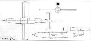
Dimensions: |
Performance: Maximum Speed: 400 mph (645kph) Target Approach: 497 mph (800kph) Range from launch at 8,200 ft. (2500m): about 205 miles (330km)
|
|
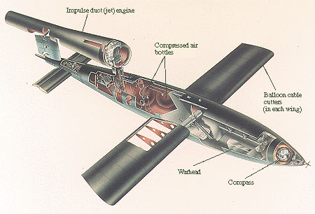
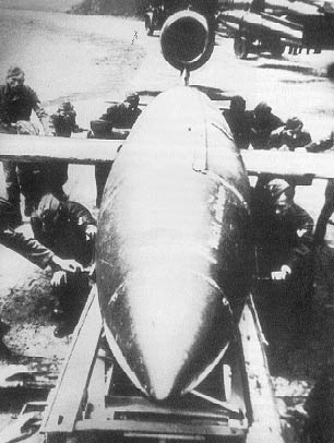
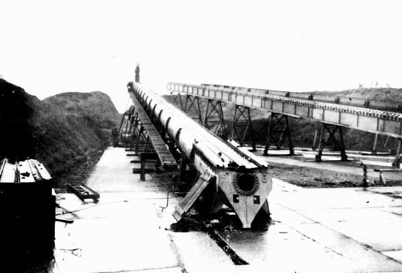
Design and Devleopment: - Source: Wikipedia The V-1 was designed by Robert Lussar of the Fieseler company and Fritz Gosslau from the Argus engine works, with a fuselage constructed mainly of welded sheet steel and wings built similarly or of plywood. The simple Pulse jet engine pulsed 50 times per second[2], and the characteristic buzzing sound gave rise to the colloquial names "buzz bomb" or "doodlebug" (after an Australian insect). It is a common myth that the V-1's pulsejet engine needed a minimum airspeed of 150 mph (241.4 kph) for operation as it is commonly confused with the Lorin ram jet. The V1's Argus Schmidt pulse jet, also known as a resonant jet, could operate at zero airspeed due to the nature of its intake vane system and accoustically tuned resonant combustion chamber. Film footage of the V1 always shows the distinctive pulsating jet exhaust of a fully running engine before the catapult system is triggered. The engine would always be started first whilst the craft was stationary on the ramp. The low static thrust of the jet engine and very high stall speed of the wings meant that the craft could not take off under its own power in a practically short distance, and thus required a catapult launch or an airlaunch from a modified bomber. Take off speed was commonly attained by launching from a ground ramp, using a chemical or steam catapult which accelerated the V-1 to 200 mph, or from a moving aircra ft such as the Heinkel He-111. The V1's pulse jet engine was also tested on a variety of craft, including an experimental attack boat known as the "Tornado". The unsuccessful prototype was a version of a sprengboot , where a boat laden with explosives was steered towards a target ship and the pilot would leap out the back at the last moment. The Tornado was assembled from surplus seaplane hulls connected in catamaran fashion with a small pilot cabin on the cross beams. The Tornado prototype was a noisy underperformer and was abandoned in favour of more conventional piston engined craft.
Guidance System: - Source: Wikipedia Target range was estimated - accurate enough for area bombing - and the detmination of when it had been reached was by a countdown timer driven by a propeller (acutally a Vane anemometer) on the nose. Before launch the counter was set to a value that would reach zero upon arrival at the target in the prevailing wind conditions. As the missile flew, the airflow turned the propellor and every 30 rotations of the propeller counted down one number on the counter. This counter triggered the arming of the warhead after about 38 miles[3]. When the count reached zero, a solenoid attached to a small guillotine was activated, cutting the air hose from the servo to the rear elevator and allowing a spring to fully depress the elevator causing the V-1 to dive[4]. While this was originally intended to be a power dive, in practice the dive caused the fuel flow to cease, which stopped the engine. The sudden silence after the buzzing alerted listeners that the missile would impact soon. With the count er determining how far the missile would fly; it was only necessary to launch the V1 with the ramp in the rough direction and the autopilot controlled the rest.
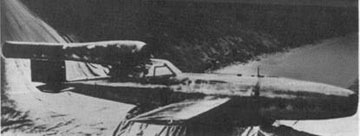
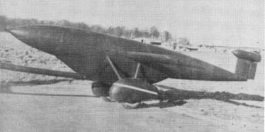
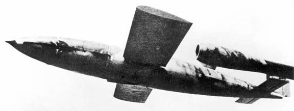
Operations: - Source: Wikipedia A myth arose that early guidance and stabilisation problems were resolved by a daring test flight by Hanna Reitsch in a V-1 modified for manned operation. The myth entered popular consciousness from Hanna's fictional exploits in the George Peppard film Operation Crossbow. Hanna's first flights in the modified V1 Fieseler Reichenberg were late in the war when she was asked to work out why test pilots were unable to land it and had died in landing attempts. Her discovery after simulated landing attempts at high altitude where there might be air space to recover, was that the craft had an extremely high stall speed and the previous pilots with little high speed experience had attempted their approaches much too slow. Her recomendations of much higher landing speeds were then introduced in training new Reichenberg volunteer pilots. The Reichenbergs air-launched rather than fired from the catapult ramp as erroneously portrayed in "Operation Crossbow". On 13 June 1944, the first V-1 struck London next to the railway bridge on Grove Road, Mile End, which now carries this plaque. Eight civilians were killed in the blast. On 13 June 1944, the first V-1 struck London next to the railway bridge on Grove Road, Mile End, which now carries this plaque. Eight civilians were killed in the blast. The conventional unpiloted V1 launch sites could theoretically launch about 15 bombs per day, although this was never consistently achieved; the record was 18 in one day. Only a quarter hit their targets due to a combination of defensive measures (see Countermeasures below), mechanical unreliability and guidance errors. Once the Allies had captured or destroyed the sites that were the principal launch points of V-1s aimed at England, the Germans switched to missile launches aimed at strategic points in the Low Countries, primarily the port of Antwerp. The earliest experimental versions of the V-1 were air-launched. Most operational V-1s were launched from static sites on land, but from July 1944 to January 1945 the Luftwaffe launched approximately 1,176 from modified Heinkel He 111 H-22s flying with the Luftwaffe's 3rd Bomber Wing or Kampfgeschwader 3 (the so-named "Blitz Wing") flying over the North Sea. Research after the war estimated a 40% failure rate of air-launched V-1s, and the He-111s used in this role were extremely vulnerable to night fighter attack, as the launch lit up the area around the aircraft for several seconds. Late in the war several air-launched piloted V-1s, known as Reichenbergs, were built, but never used in combat. There were plans, not carried into practice, to use the Arado Ar 234 jet bomber to launch V-1s either by towing them aloft or by launching them from a "piggy back" position atop the aircraft.
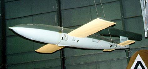
Almost 30,000 V-1s were made. Approximately 10,000 were fired at England; 2,419 reached London, killing about 6,184 people and injuring 17,981. The greatest density of hits were received by Croydon, on the SE fringe of London. |
Additional Images
|
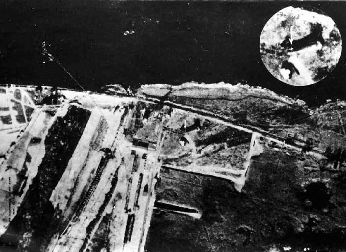
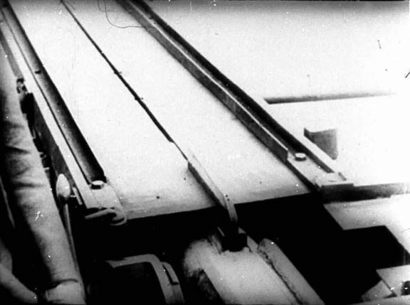
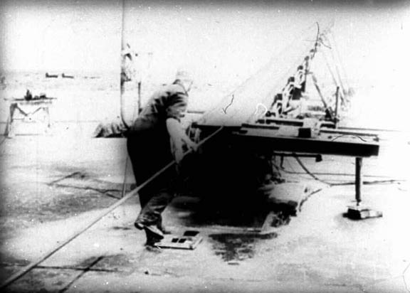
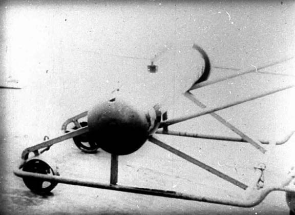
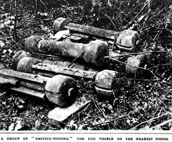
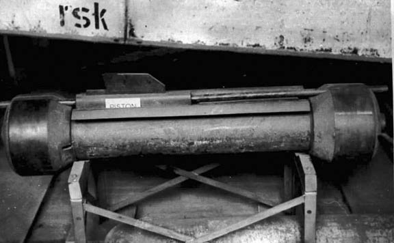
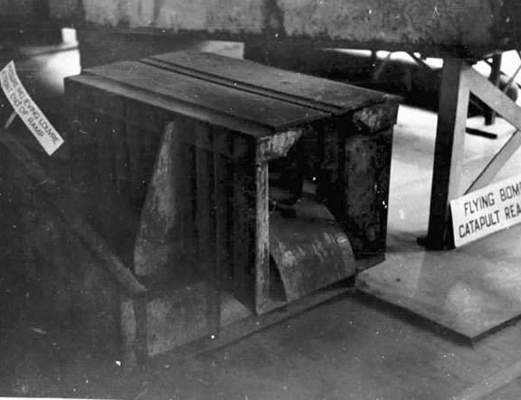
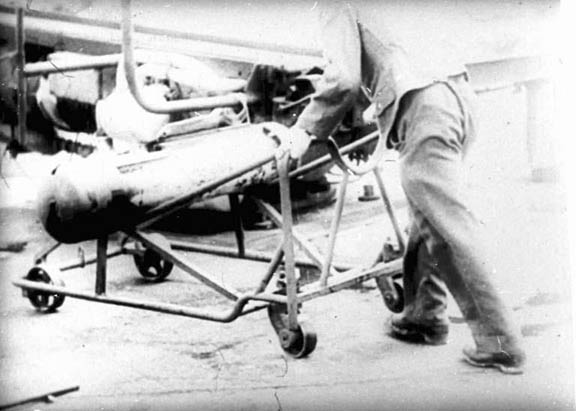
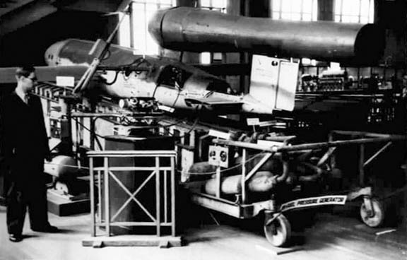
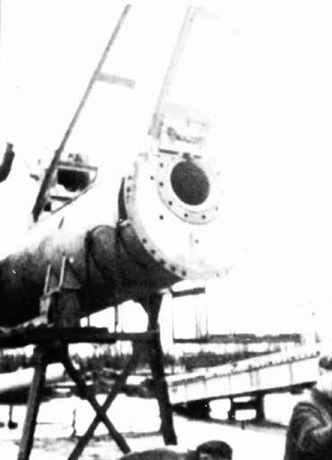
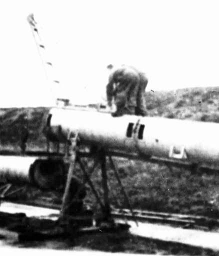
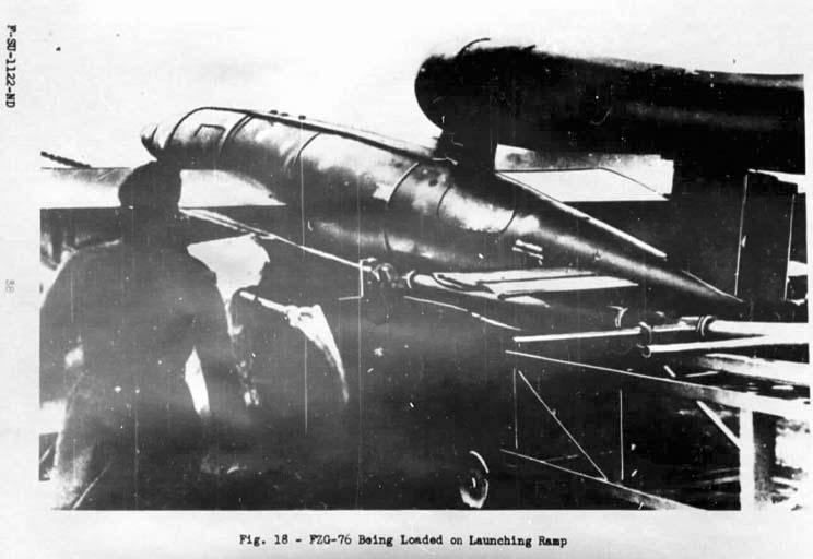
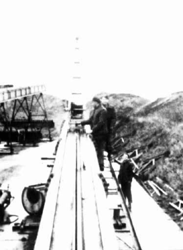
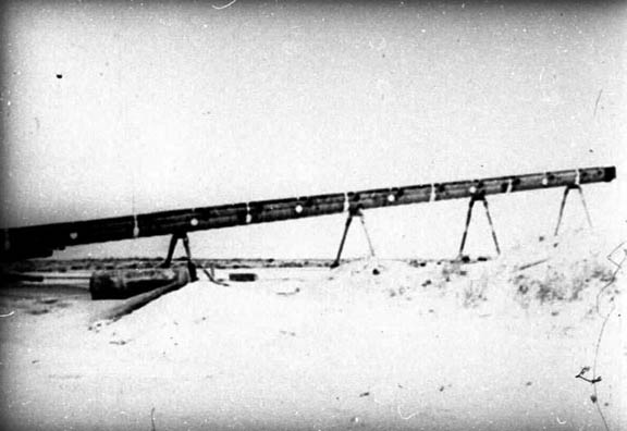
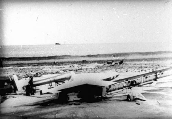
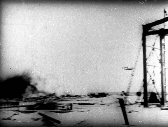
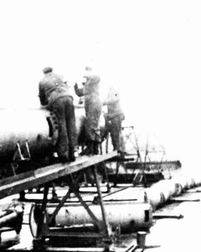
Image 1 - The V-1 launch rail at the Imperial War Museum Image 2 - The V-1 launch rail at the Imperial War Museum Image 3 - The JB-2 "Loon" (Fi-103/V-1 Missile) at the USAF Museum. Image 4 - V-1 On display at unknown museum. Image 5 - Three view drawing Image 6 - V-1 On stand. Image 7 - Shot of V-1 on launch rail, front view. Image 8 - V-1 production line. Image 9 - Manned test airframe. Image 10 - V-1 airframe converted into a towed fuel tank. Image 11 - V-1 towed fuel tank behind a Ar 234. Image 12 - V-1 in flight. Image 13 - Recon photo of launch site. Image 14 - Close up of launch rail. Image 15 - Launch rail with crewman. Image 16 - Launch rail with crewmen. Image 17 - Loading launch piston. Image 18 - Launch piston. Image 19 - Pile of launch pistons. Image 20 - Good shot of launch piston. Image 21 - Section of rail on display after war. |
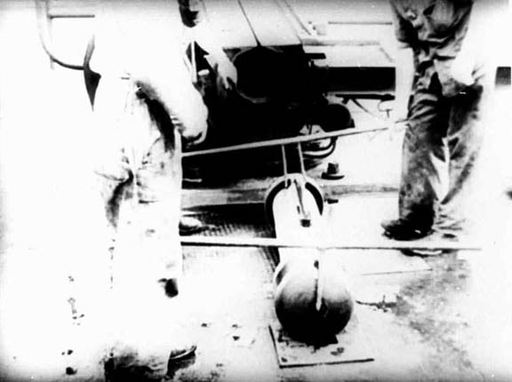
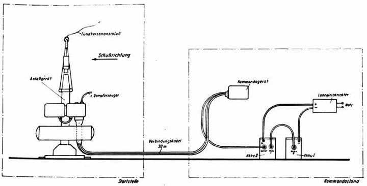
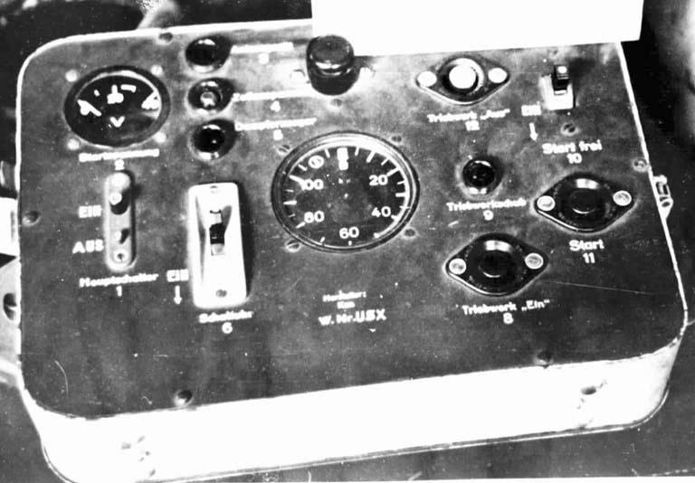
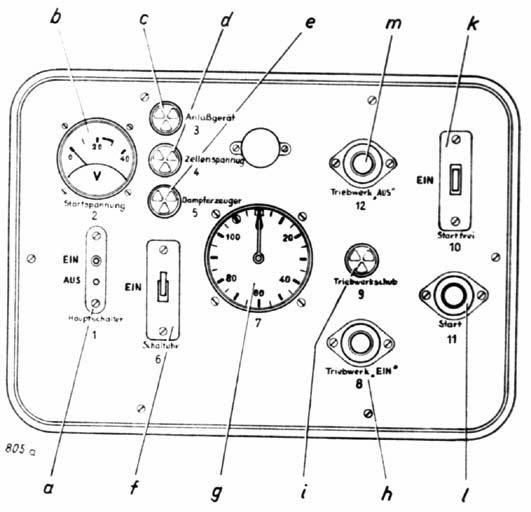
Image 22 - Piston on handling cart. Image 23 - V-1 on display after war. Image 24 - End of piston tube. Image 25 - Assembling a launch rail. Image 26 - V-1 being loaded on launch rail. Image 27 - Launch rail. Image 28 - Assembling a launch rail. Image 29 - Launch rail. Image 30 - V-1 prepped for launch. Image 31 - V-1 beginning catapult launch. Image 32 - V-1 dropping piston after launch. Image 33 - V-1 leaving launch rail. Image 34 - V-1 launch controls. Image 35 - Preparing to test the V-1. Image 36 - Assembling the launch rail. Image 37 - V-1 on display after war. Image 38 - Two launch rail. Image 39 - Parts diagrams. Image 40 - Parts diagrams. Image 41 - Control box. Image 42 - Diagram of control box. |
LUFTWAFFE RESOURCE CENTER > MISSILES > PREVIOUS PAGE